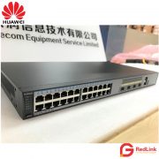
Huawei Switch S6720-30C-EI-24S
$2,980.00 $2,480.00
Brand: Huawei
Model: S6720-30C-EI-24S
Detail: Huawei S6720-30C-EI-24S-AC
Condition: 100% New
Availability: IN STOCK
- Description
- Features
- Ordering information
- Inquiry
S6720-30C-EI-24S-AC
Version Mapping
Table 1 lists the mapping between the S6720-30C-EI-24S-AC chassis and software versions.
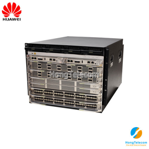
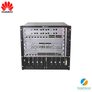
Appearance and Structure

Similar products: S6720-54C-EI-48S-AC
S5720S-SI
S5720S-52P-SI-AC
S5720S-28X-SI-AC
S5720S-28X-SI-DC
S5720S-52X-SI-AC
S5720S-52X-SI-DC

Port Description
10GE SFP+ port
A 10GE SFP+ Ethernet optical port supports auto-sensing to 1000 Mbit/s. It sends and receives service data at 1000 Mbit/s or 10 Gbit/s. Table 2 describes the attributes of a 10GE SFP+ Ethernet optical port.
40GE QSFP+ port
A 40GE QSFP+ optical port sends and receives service traffic at 40 Gbit/s and can be split into four 10GE ports. After a split, 40GE QSFP+ optical port needs to be connected to a remote device using a 1-to-4 QSFP+ fiber (with matching optical modules), 1-to-4 QSFP+ AOC cable, or a 1-to-4 QSFP+ copper cable. Table 3 describes the attributes of a 40GE QSFP+ optical port.
Console port
The console port is connected to a console for on-site configuration. The port must use a console cable. The console port is used when a switch is powered on for the first time. For details about the attributes of a console port, see Table 4.
ETH management port
You can connect a switch to a configuration terminal or network management workstation through the ETH management port to configure the switch locally or remotely. The port must use an Ethernet cable. You can choose to download the software package through the ETH management port in the BootLoad menu. File transfer through the ETH management port is faster than transfer through the console port. For details on how to use the ETH management port, see the Configuration Guide - Basic Configurations. Table 5 describes the attributes of an ETH management port.
USB port
The USB port can have a USB flash drive connected to upgrade the switch, or transfer configuration files or other files. The USB port can only connect to a USB flash drive that complies with USB 2.0.
![]() NOTE:
NOTE:
Indicator Description
![]() NOTE:
NOTE:
Hold down the mode switch button for 6s and release it to start the web initial login mode. Either of the following situations will occur:
- If the switch has no configuration file, the system attempts to enter the web initial login mode. In this mode, the status of mode indicators is as follows:
- If the system enters the web initial login mode successfully, all mode indicators turn green and stay on for a maximum of 10 minutes.
- If the system fails to enter the initial login mode, all mode indicators fast blink for 10 seconds and then restore to the default status.
- If the switch has a configuration file, the system cannot enter the web initial login mode. In this case, all mode indicators fast blink for 10s, and then return to the default states.

![]() NOTE:
NOTE:
The S6720-EI series switches provide a command for setting fault indicators, which help field maintenance personnel find a faulty switch quickly.
The SYS indicator and mode indicators (STAT, SPED, and STCK) are used as fault indicators. When an S6720-EI switch is faulty, you can run the command to turn on the fault indicators. Then the SYS indicator and mode indicators fast blink red to help field maintenance personnel quickly find the faulty switch.
| No. | Indicator | Name | Color | Status | Description |
|---|---|---|---|---|---|
| 1 | PWR1 | Power module indicator | - | Off | No power module is available in power module slot 1, or the switch has only one power module but the power module does not work normally. |
| Green | Steady on | A power module is installed in power module slot 1 and is working normally. | |||
| Yellow | Steady on | The switch has two power modules installed. Any of the following situations occurs in power module slot 1:
|
|||
| 2 | PWR2 | Power module indicator | - | Off | No power module is available in power module slot 2, or the switch has only one power module but the power module does not work normally. |
| Green | Steady on | A power module is installed in power module slot 2 and is working normally. | |||
| Yellow | Steady on | The switch has two power modules installed. Any of the following situations occurs in power module slot 2:
|
|||
| 3 | SYS | System status indicator | - | Off | The system is not running. |
| Green | Fast blinking | The system is starting. | |||
| Green | Slow blinking | The system is running normally. | |||
| Red | Steady on | The system does not work normally after registration, or a fan alarm or temperature alarm has been generated. | |||
| 4 | STAT | Status indicator | - | Off | The status mode is not selected. |
| Green | Steady on | The status mode (default mode) is selected. If the status mode is selected, the service port indicator shows the port link or activity state. | |||
| 5 | SPED | Speed indicator | - | Off | The speed mode is not selected. |
| Green | Steady on | The service port indicators show the port speeds. After 45 seconds, the service port indicators automatically restore to the status mode. | |||
| 6 | STCK | Stack indicator | - | Off |
|
| Green | Steady on | The switch is a standby or slave switch in a stack, and the service port indicators show the stack ID of the switch. | |||
| Green | Blinking |
After 45 seconds, the service port indicators automatically restore to the status mode. |
|||
| 7 | MODE | Mode switch button | - | - |
If you do not press the MODE button within 45 seconds, the service port indicators restore to the default mode. In this case, the STAT indicator is steady green, the SPED indicator is off, and the STCK indicator is off or blinking green. |
| 8 | - | 10GE service port indicator (two indicators for each port) | Meanings of service port indicators vary in different modes. For details, see Table 7. | ||
| 9 | - | 40GE service port indicator (one indicator for each port) | Meanings of service port indicators vary in different modes. For details, see Table 8. | ||
| 10 | - | ETH port indicator | - | Off | The ETH port is not connected. |
| Green | Steady on | The ETH port is connected. | |||
| Green | Blinking | The ETH port is sending or receiving data. | |||
| 11 | - | USB-based deployment indicator | - | Off |
|
| Green | Steady on | A USB-based deployment has been completed. | |||
| Green | Blinking | The system is reading data from the USB flash drive. | |||
| Yellow | Steady on | The switch has copied all the required files and completed the file check. The USB flash drive can be removed from the switch. | |||
| Red | Blinking | An error has occurred when the system is executing the configuration file or reading data from the USB flash drive. | |||
| Display Mode | Color | Status | Description |
|---|---|---|---|
| Status | - | Off | The port is not connected or has been shut down. |
| Green | Steady on | A link has been established on the port. | |
| Yellow | Blinking | The port is sending or receiving data. | |
| Speed | - | Off | The port is not connected or has been shut down. |
| Green and yellow | Steady on | 1000M/10GE port: The port is operating at 1000 Mbit/s. | |
| Green and yellow | Blinking | 1000M/10GE port: The port is operating at 10 Gbit/s. | |
| Stack | - | Off | Port indicators do not show the stack ID of the switch. |
| Green and yellow | Steady on |
The switch is not the master switch in a stack.
|
|
| Green and yellow | Blinking |
The switch is the master switch in a stack.
|
| Display Mode | Color | Status | Description |
|---|---|---|---|
| Status | - | Off | The port is not connected or has been shut down. |
| Green | Steady on | A link has been established on the port. | |
| Green | Blinking | The port is sending or receiving data. | |
| Speed | - | Off | The port is not connected or has been shut down. |
| Green | Steady on | The port is operating at 10 Gbit/s. | |
| Green | Blinking | The port is operating at 40 Gbit/s. |
Power Supply Configuration
The S6720-30C-EI-24S-AC can be configured with a single power module or double power modules for 1+1 power redundancy. AC and DC power modules can be used together in the same switch.
Figure 3 shows the power supply connections of dual DC power modules. After DC power is transmitted to the PWR module, the PWR module provides 12 V output voltage, and the motherboard provides power for the entire device.


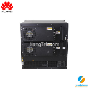
Heat Dissipation
The S6720-30C-EI-24S-AC uses pluggable fan modules for forced air cooling. Air flows in from the left side, right side, and front panel, and exhausts from the rear panel.

![]() NOTE:
NOTE:
Technical Specifications
Table 9 lists technical specifications of the S6720-30C-EI-24S-AC.
Model: S6720-30C-EI-24S
Detail: Huawei S6720-30C-EI-24S-AC
Availability: IN STOCK
Related Products
-
LS-S2309TP-PWR-EI
$250.00Brand: Huawei
Model: LS-S2309TP-PWR-EI
Detail: 02351812 Huawei S2300 Series Switch S2309TP-PWR-EI Mainframe(8 10/100 BASE-T ports and 1 Combo GE(10/100/1000 BASE-T+100/1000 Base-X) ports ,PoE and AC 110/220V)
Condition: Brand New Sealed
Availability: IN STOCK
-
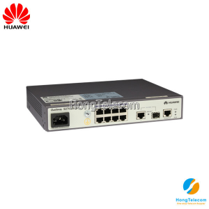
S1700-8-AC
$18.00Brand: Huawei
Model: S1700-8-AC
Detail: 98010454 Huawei Quidway S1700 Switch S1700-8-AC (S1700-8 Mainframe 8 10/100Base-T,AC adapter)
Condition: Brand New Sealed
Availability: IN STOCK
-
CE5850-HI-B00
$4,380.00Brand: Huawei
Model: CE5850-HI-B00
Detail: CE5850-HI-B00 Huawei CE5800 Series Data Center Switch CE5850-48T4S2Q-HI (2*150W AC Power Module,2*FAN Box,Port side exhaust)
Condition: Brand New Sealed
Availability: IN STOCK
-
S7703 Assembly Chassis
$3,000.00Brand: Huawei
Model: ES0B00770300
Detail: 02113304 Huawei S7700 Switch S7703 Assembly Chassis ES0B00770300 For Huawei S7703
Condition: Brand New Sealed
Availability: IN STOCK
-
EH1BS9703E00
$1,380.00Brand: Huawei
Model: EH1BS9703E00
Detail: 02113547 Huawei S9700 Series Switch EH1BS9703E00 S9703 Assembly Chassis, 3 Slots
Condition: Brand New Sealed
Availability: IN STOCK
-
S5700-28C-HI-AC
$2,500.00Brand: Huawei
Model: S5700-28C-HI-AC
Detail: 03021PED Huawei S5700 Series Switch S5700-28C-HI-AC(24 Ethernet 10/100/1000 ports,with 1 interface slot,with 170W AC power supply)
Condition: Brand New Sealed
Availability: IN STOCK
-
S2700-9TP-SI-AC
$80.00Model: S2700-9TP-SI-AC
Detail: S2700-9TP-SI-AC 02352337 Huawei Quidway S2700 Switch
Condition: Brand New Sealed
Availability: IN STOCK
-
S3700-28TP-SI-AC
$300.00Brand: Huawei
Model: S3700-28TP-SI-AC
Detail: 02352365 Huawei Quidway S3700 Switch S3700-28TP-SI-AC Mainframe(24 Ethernet 10/100 ports, 2 Gig SFP and 2 dual-purpose 10/100/1000 or SFP, AC 110/220V)
Condition: Brand New Sealed
Availability: IN STOCK
-
CE12804-AC
$4,820.00Brand: Huawei
Model: CE12804-AC
Detail: Huawei CE12800 Series Data Center Switch CE12804 AC Assembly Chassis(with CMUs and Fans)
Condition: Brand New Sealed
Availability: IN STOCK
-
ET1Z04EACC00
$6,900.00Brand: Huawei
Model: ET1Z04EACC00
Detail: 02350MJA Huawei S12704 Enhanced Engine AC Bundle(Including Assembly Chassis*1,MPUA Main Board*1,SFUC Switch Fabric Unit*2,800W AC Power*2,Basic Software*1)
Condition: Brand New Sealed
Availability: IN STOCK