


Huawei OLT EA5800-X15
$3,600.00 $2,700.00
Brand: Huawei
Model: EA5800-X15
Detail: Huawei OLT EA5800 Series EA5800-X2/X7/X15/X17
Condition: 100% New
Availability: IN STOCK
- Description
- Features
- Ordering information
- Inquiry
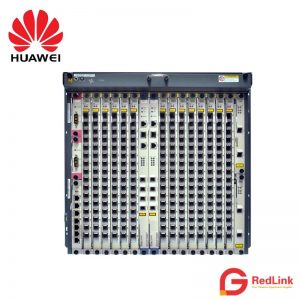
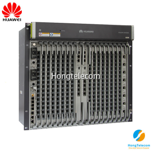
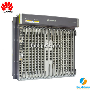
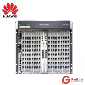
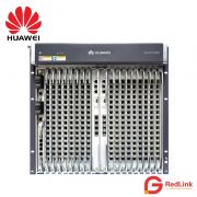
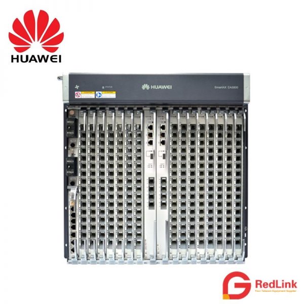
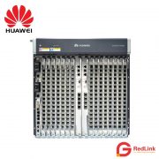
Appearance and Structure
The EA5800-X15 service subrack provides 20 slots, and has a fan tray at the top. The subrack is installed in the cabinet through the mounting brackets.

Similar products:EA5800-X17 EA5800-X7 EA5800-X2

ESD Jack
The ESD jack of the EA5800-X15 subrack is on the left of the fan tray, which is used to connect the ESD wrist strap to prevent device damage caused by electrostatic discharge.
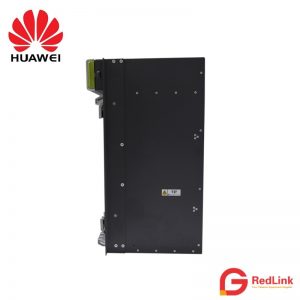
Grounding

Connect the ground cables properly to guarantee protection against lightening and interference for the EA5800-X15 subrack. When a Huawei cabinet is installed, the service subrack is grounded through mounting ears and therefore no separate ground cables are required. When a third-party cabinet is installed, the separate ground cable needs to be connected to the service subrack and ground point on the cabinet.
EA5800-X15 subrack has 2 ground points. One is on the side panel and the other is at the bottom of the right mounting ear of the subrack.
The power input end of the EA5800-X15 subrack has a noise filter. The center ground of the noise filter connects to the subrack, called the subrack ground, that is, the protection ground. Ground the subrack securely so that the influence electricity, leakage electricity can flow to the ground, improving the protection against electromagnetic interference.
Use a ground cable to connect the ground point of the subrack to the ground bar of the telecommunications room or to the ground directly. It is recommended that the grounding resistance of the telecommunications room should be less than 10 ohms. Refer to the local standards to ground the subrack.
Physical Specifications
This topic provides the dimensions, weight, power supply specifications and power consumption of the EA5800-X15 service subrack.
Dimensions and Weight
| Specification | Value |
|---|---|
| Dimensions (H x W x D, including mounting ears) | 486 mm x 482.6 mm x 287 mm |
| Dimensions (H x W x D, excluding mounting ears) | 486 mm x 442 mm x 287 mm |
| Maximum weight at full configuration (including mounting ears) | 35 kg |
Power Supply
Power Consumption
| Typical Configuration | Static power consumption | Maximum power consumption | Typical power consumption | Board configuration |
|---|---|---|---|---|
| GPON | 513 | 1182 | 847.5 | H902MPLAE*2+H901OGHK+H901PILA*2+H901FMLA+H901GPSFE*14 |
![]() NOTE:
NOTE:
The power consumption of a service subrack is calculated based on the following conditions:
- Operating voltage: -53.5 V DC.
- Ambient temperature: 25°C.
- Static power consumption: All ports do not carry any loads and optical modules are not installed on optical ports.
- Maximum power consumption: All ports fully carry loads.
- Typical power consumption: half of the total value of static power consumption and maximum power consumption.
- In the case of Access device, power consumption is generally transformed into heat consumption. Hence, heat consumption (BTU/h) and power consumption (W) can be converted to each other in the formula: 1 BTU/h = 0.2931 W.
Slot Configuration
An EA5800-X15 service subrack provides 20 slots, including 2 slots for control boards, 2 slots for power boards, 1 slot for the universal interface board, and 15 slots for service boards.
H901BPIB is the backplane supported by the EA5800-X15 service subrack.

Table 1 lists the configuration of boards in the EA5800-X15 service subrack.
| Slot Type | Slot | Supported Board | Remarks |
|---|
| Slot Type | Slot | Supported Board | Remarks |
|---|---|---|---|
| Control board slot | 8,9 | Control board | The device is configured with both active and standby control boards of the same type in 2 slots. |
| Power board slot | 18,19 | Power board | - |
| Universal interface board slot | 0 | Universal interface board | - |
| Service board slot | 1–7,10–17 |
|
|
Fan Tray
The fan tray of the EA5800-X15 service subrack has six fans and fan monitoring board FMLA, and functions heat dissipation, monitoring, and fan speed adjustment, which ensures that the device works at a stable temperature.

Specification
| Item | Specification |
|---|---|
| Dimensions (W x D x H) | 448 mm x 284 mm x 76 mm |
| Weight | 4.90 kg (Fan tray) |
| Power consumption | H901FMLA:
|
![]() NOTE:
NOTE:
In the case of Access device, power consumption is generally transformed into heat consumption. Hence, heat consumption (BTU/h) and power consumption (W) can be converted to each other in the formula: 1 BTU/h = 0.2931 W.
Function
The functions of the fan tray are as follows:
- Heat dissipationThe fan tray is at the top of the service subrack and exhausts hot air for heat dissipation. The cool air flows to the subrack from the bottom of the subrack and then is exhausted from the top of the subrack after passing the boards.
- MonitoringThe fan tray is configured with the fan monitoring board to detect whether the fans are working in the normal state. The fan monitoring board also provides the port for communication with the control board. The detected information is transmitted to the control board through the fan monitoring board periodically.
- Speed adjustmentThe rotating speed of the fans can be adjusted according to the detected temperature automatically or be adjusted by setting the related data manually.
Indicator
| Indicator | Color | Status | Meaning | Operation Description |
|---|
| Indicator | Color | Status | Meaning | Operation Description |
|---|---|---|---|---|
| STATUS | Yellow | Blinking quickly (on for 0.125 s and off for 0.125 s repeatedly) | The fan tray is not registered, is being loaded, or fails to communicate with the control board. |
|
| Green | Blinking | The fan tray works in the normal state. | No action is required. | |
| Yellow | Blinking slowly (on for 1 s and off for 1 s repeatedly) | The fan tray generates alarms that do not affect services. | Handle it based on the corresponding alarm. | |
| Red | Blinking | The fan tray is faulty or the fan tray generates an over-temperature alarm. |
|
Fan Speed Adjustment
Set the fan speed adjustment mode to "automatic" or "manual" in the command line interface (CLI). After the fans are installed, they work in automatic mode by default.
- Automatic mode
- Control-system-triggering: The control system automatically adjusts the fan speed according to the board temperatures for energy conservation.
- Monitoring-board-triggering: The control system adjusts the fan speed according to the temperature information collected by the monitoring board.
 NOTE:
NOTE:The automatic mode has two variants (automatically selected by the system): control-system-triggering and monitoring-board-triggering.
- Manual modeCommands are executed to adjust the fan speed. The levels range from 0 to 6, level 0 being the lowest speed and level 6 being the highest speed. Alternatively, the fan speed can be set from 30% to 100%.
Heat Dissipation
This topic describes the ventilation of the EA5800-X15 service subrack.
The EA5800-X15 service subrack has a fan tray at the top to exhaust hot air for heat dissipation.
The airflow is as follows: The cool air enters the EA5800-X15 service subrack at the bottom, and is blown towards the top side by the fans, and finally, exits at the top side of the EA5800-X15 service subrack.Figure 1 shows the heat dissipation of the EA5800-X15 service subrack.

Model: EA5800-X15
Detail: Huawei OLT EA5800 Series EA5800-X2/X7/X15/X17
Availability: IN STOCK
Related Products
-
Huawei MDU MA5626
Brand: Huawei
Model: MA5626-24 POE
Detail: HUAWEI MA5626 MDU GPON ONU
Condition: 100% New
Availability: IN STOCK
$588.00$288.00 -
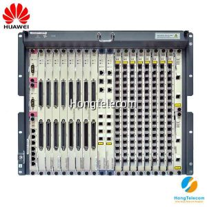
HUAWEI OLT MA5680T IEC Service Subrack
Brand: Huawei
Model: MA5680T
Detail: IEC service subrack Optical Line Terminal MA5680T (SCUN / SCUK + PRTE) OLT from Huawei
Condition: 100% New
Availability: IN STOCK
$2,900.00$2,400.00 -
Huawei GPON OLT MA5800-X2/X7/X15/17
Model: MA5800 Series
Detail: Original Newest Huawei Optical Line Terminal GPON MA5800
Condition: 100% New
Availability: IN STOCK
$3,800.00$2,200.00 -
Huawei MDU MA5671
Brand: Huawei
Model: MA5671
Detail: HUAWEI MA5671 1000M Ethernet Port ONU
Condition: 100% New
Availability: IN STOCK
$288.00$100.00 -
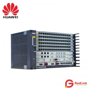
HUAWEI GPON OLT MA5608T
Brand: Huawei
Model: MA5608T
Detail: 19Inch 1U Mini Optical Line Terminal MA5608T OLT
Condition: 100% New
Availability: IN STOCK
$2,500.00$2,100.00 -
Huawei OLT MA5800-X17
Brand: Huawei
Model: MA5800-X17
Detail: MA5800-X17 (MPLA + PILA) and Main Control OLT from Huawei
Condition: 100% New
Availability: IN STOCK
$3,200.00$2,600.00 -
Huawei OLT MA5606T
Brand: Huawei
Model: MA5606T
Detail: MA5606T (MCUA + MPWA) OLT from Huawei
Condition: 100% New
Availability: IN STOCK
$2,600.00$2,000.00 -
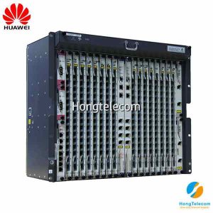
HUAWEI OLT MA5600T ETSI Service Subrack
Brand: Huawei
Model: MA5600T
Detail: ETSI service subrack Optical Line Terminal MA5600T (SCUN / SCUK + PRTE) and Main Control OLT from Huawei
Condition: 100% New
Availability: IN STOCK
$2,900.00$2,400.00 -
Huawei GPON OLT MA5600T
Model: MA5600T
Detail: Original Newest Huawei Optical Line Terminal GPON MA5600T
Condition: 100% New
Availability: IN STOCK
$3,800.00$2,800.00 -
HUAWEI OLT MA5683T
Brand: Huawei
Model: MA5683T
Detail: MA5683T (SCUN / SCUK + PRTE) OLT from Huawei
Condition: 100% New
Availability: IN STOCK
$2,600.00$2,200.00